How to Choose the Right Alarm Cable for Your Project?
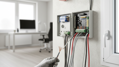
Choosing the right alarm cable is more than selecting the thickest wire on a supplier’s shelf. It requires matching the cable to the alarm system, installation environment, and approved project requirements. A security panel in a quiet office has different needs from a fire alarm circuit running through a hot, crowded ceiling. Cable length, conductor size, voltage drop, shielding, temperature rating, and mechanical protection all affect dependable performance. Small details matter, especially at terminal blocks and junction points.
Alarm-cable specialist Dr. Ian Moore explains, “A cable is not just a wire; it is part of the alarm system’s safety margin.” That principle deserves attention. A cable may look professional while still having unsuitable insulation, poor interference resistance, or inadequate fire performance. The tempting choice is often the cheapest compliant-looking product. That choice can become expensive during testing or future maintenance.
This guide examines how to compare alarm cable specifications with practical project conditions. It considers fire-rated designs, screened and unscreened options, conductor gauges, installation distances, and compatibility with sensors, panels, and notification devices. Always check the manufacturer’s datasheet and the requirements of the applicable local authority. Product labels can be confusing. Even experienced installers can overlook one line of technical information. A careful decision records the cable type, route, operating temperature, and expected electrical load before installation begins. There is no universal best cable. The right choice is the one that remains reliable under real conditions, not merely the one that looks suitable in a catalogue.
Define Your Alarm System’s Cable Requirements
Choosing the right alarm cable begins with defining the system’s actual requirements. Identify the alarm type, operating voltage, standby duration, maximum cable length, and connected load. A notification circuit carrying sounders needs different capacity than a low-current initiating circuit. Record every device and calculate voltage drop at the farthest point. A cable that works on the bench may fail after a long corridor and several junctions.
Safety performance matters as much as conductor size. NFPA’s Fire Loss in the United States During 2022 reported approximately 1,504,500 fires and 3,790 civilian fire deaths. This data reinforces why alarm pathways must remain dependable during emergencies. Review NFPA 72 requirements for circuit integrity, pathway survivability, separation, and installation methods. Select the required fire-resistance rating for the building conditions. Check whether the route passes through plenum spaces, risers, damp areas, or zones with electromagnetic interference.
Think about installation realities. Measure the route, not the floor plan. Leave practical service length at panels and devices. Use twisted or shielded construction only when the system design requires it; extra shielding can add cost and complicate termination. Confirm conductor material, insulation temperature, polarity, and compatibility with terminals. Industry training guidance from BICSI emphasizes documented pathways and administration records, yet many projects still rely on informal cable notes. That is a weakness. Recheck the calculation after field changes, because one added detector or relocated sounder can alter the final voltage margin.
Compare Alarm Cable Types and Conductor Configurations
Choosing alarm cable starts with the signal, distance, and installation environment.
NFPA’s Fire Loss in the United States During 2022 recorded 1,504,500 fires. That figure makes dependable transmission more than a specification exercise. Solid conductors suit fixed routes and provide stable termination. Stranded conductors bend more easily inside cabinets and moving equipment. They can, however, loosen under repeated vibration. Inspectors should verify terminal compatibility.
Conductor configuration also changes performance.
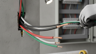
A two-core cable supports many conventional detection circuits. Four-core cable can separate power and signal paths, simplifying some supervised systems. Twisted pairs help reduce electromagnetic interference on longer runs. Shielded cable may help near motors, inverters, or fluorescent equipment, but poor grounding can create new noise.
Small mistakes matter.
Cable size must match voltage drop, loop length, alarm load, and local code requirements.
IEC 60331 evaluates circuit integrity during fire exposure, while installation rules may require additional resistance and survivability tests. Do not treat “fire-rated” as a universal approval. Check the exact test method, temperature, duration, and mounting condition. A 1.5 mm² conductor may work in one layout, yet fail after longer routing or heavier notification loads. That is an easy assumption to challenge. Review the manufacturer’s resistance data, then confirm the calculation on site before closing the ceiling.
Evaluate Electrical Performance and Environmental Resistance
How to Choose the Right Alarm Cable for Your Project?
Alarm cable selection should begin with electrical performance, not price. Check conductor resistance, voltage drop, capacitance, and signal integrity at the planned installation length. A cable that works on a test bench may fail across a long, crowded pathway. Shielding can reduce electromagnetic interference, but poor grounding may create new problems. Keep the circuit stable.
NFPA’s Fire Loss in the United States During 2022 reported approximately 1.5 million fires and $18.1 billion in property damage. These figures highlight why alarm circuits must remain dependable during emergencies. Choose cable with a suitable voltage rating and verified flame-performance data. IEC 60331 testing evaluates circuit integrity under fire exposure, while IEC 60332 addresses flame propagation. These tests measure different risks. They should not be treated as interchangeable.
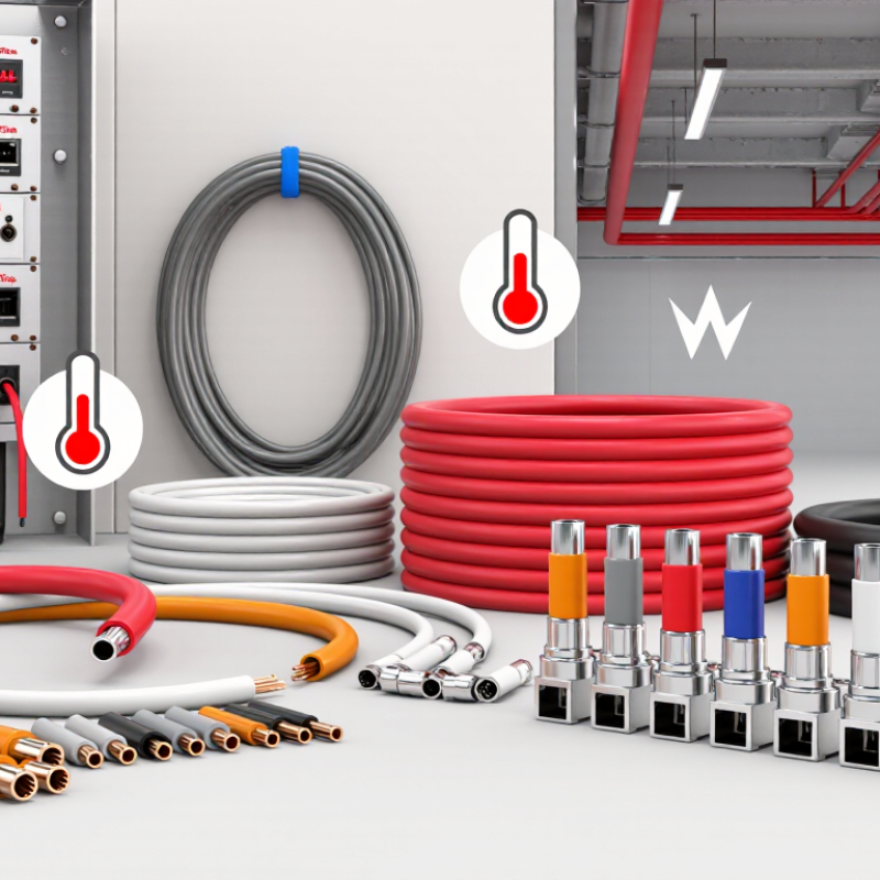
Environmental resistance needs equal attention. Review the cable’s temperature range, moisture protection, UV resistance, and resistance to corrosive gases. Outdoor routes may face sunlight, rain, and sharp temperature changes. Industrial spaces can add oil vapors or chemical dust. A plenum installation also requires the correct low-smoke, flame-spread classification. Do not rely on a familiar cable type. Field inspections often uncover crushed jackets, excessive bend radius, or unsealed entries. The specification may look correct, yet installation conditions can still defeat it. Recheck the route, termination method, and local code requirements before approval.
How to Choose the Right Alarm Cable for Your Project?
Compare conductor resistance at 20°C with a representative insulation temperature rating. Lower resistance helps reduce voltage drop over long alarm circuits, while a higher temperature rating can provide greater environmental tolerance. Values are typical engineering references; always verify the final cable datasheet and applicable installation standards.
AWG conductor resistance values are based on nominal copper resistance at 20°C. The temperature figures represent common insulation-system ratings and should not be treated as a complete measure of water, UV, chemical, or mechanical resistance.
Check Safety Standards, Certifications, and Compatibility
Choosing alarm cable should begin with safety standards, not price or color.
NFPA 72 defines installation and performance principles for fire alarm systems, while electrical codes govern routing, separation, and circuit protection. In North America, verify whether the cable carries the required fire alarm listing for its location. Other markets may require EN or IEC-based compliance. IEC 60332 addresses flame spread, while IEC 60754 and IEC 61034 address corrosive gases and smoke density. These details matter inside a narrow ceiling space.
The risk is measurable.
NFPA’s Fire Loss in the United States, 2023 report recorded about 1.39 million fires and approximately 3,670 civilian fire deaths. Cable choice cannot prevent every incident, but compliant materials support signal continuity during emergencies. Check conductor size, voltage rating, capacitance, shielding, and temperature range. Then compare them with the control panel and connected detectors. A cable may be certified, yet still be incompatible.
Do not trust a printed label alone. Request current test evidence, certification records, and installation instructions from the supplier. Inspect the cable jacket for identification, damage, and moisture exposure. Keep power and alarm circuits separated where required. A practical commissioning lesson is simple: test the longest circuit, not only the nearest device. Small assumptions cause large failures. I would recheck compatibility after every panel change. Clearance rules are easy to overlook.