How to Choose the Right Cable Loom for Your Project?

Choosing the right cable loom is not a cosmetic decision. It affects protection, routing, service life, and installation speed. A loom may look tidy on a workbench, yet fail beside a hot engine, sharp bracket, or vibrating machine. The correct choice begins with the working environment.

Henry W. Ott, a respected EMC engineering authority, wrote, “The most important EMC principle is to minimize loop area.” That principle matters when selecting a cable loom. A well-designed loom can keep conductors grouped, reduce movement, and support cleaner routing. It cannot fix poor grounding or incorrect cable placement. That part is often overlooked.

Start with temperature. Check the loom’s continuous and peak temperature ratings. Then examine abrasion, oil, moisture, chemicals, and ultraviolet exposure. Nylon sleeving may suit a dry control cabinet. It may degrade quickly near fuel, hydraulic fluid, or engine heat. Braided PET offers flexibility and easy branch-outs. Conduit provides stronger mechanical protection, but it can be harder to inspect and terminate.

Measure the harness before ordering. Include bends, connectors, clips, and service loops. A loom that fits tightly may strain terminals. One that is too loose can rub against nearby surfaces. Small details matter.

Think about maintenance, too. Can technicians open the sleeve without removing the entire harness? Can they identify each branch after six months? Labels, color coding, and reliable fastening points save time.

There is no universal best option. That is the uncomfortable truth. Project teams sometimes choose the cheapest cable loom, then pay more through failures and rework. A better decision balances material, protection, flexibility, assembly effort, and expected service life. Recheck the choice against real conditions, not only the drawing.
How to Choose the Right Cable Loom for Your Project?

Define the Loom’s Voltage, Current, Temperature, and Environment

Choosing the right cable loom starts with four practical questions: What voltage will it carry? What current will flow? How hot will it become? What environment will surround it?

Voltage determines the loom’s insulation requirements. A loom rated too low may suffer arcing or insulation failure. Current affects conductor size and heat generation. Measure the continuous load, then account for startup surges. I have seen small motors overheat looms that looked adequate on paper.

A quick estimate is tempting. It can mislead. Use the cable length, conductor material, installation method, and acceptable voltage drop when selecting wire size. Leave room for future load changes, but avoid excessive size that makes routing difficult.

Temperature changes performance. High heat can soften insulation and reduce its service life. Low temperatures may make jackets stiff and prone to cracking during movement. Check the expected temperature near engines, heaters, outdoor panels, or sealed enclosures. Environment matters just as much. Moisture, oil, dust, vibration, and repeated bending each demand suitable protection. A woven sleeve may work inside a dry control cabinet but fail near sharp metal edges. Flexible conduit may protect better in that location. Inspect the loom after installation, not only during assembly. I once overlooked a tight bend behind a panel; the loom passed initial testing, yet the routing created unnecessary strain. That mistake changed how I review clearance and movement.
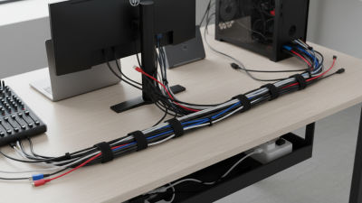

Match Wire Size to Ampacity and Apply NEC 40% Raceway Fill Limits

Choosing a cable loom starts with the conductors inside it, not the loom’s appearance. I begin by listing each wire’s load, insulation rating, length, and installation environment. Ampacity must suit the expected current after correction factors are applied. Heat matters. A crowded loom can retain heat, reducing practical capacity and accelerating insulation damage. I once selected a neat sleeve for a compact control panel and underestimated bundled conductors. The wiring passed a bench test, but the design needed a larger enclosure and better separation.

Match wire size to the allowable ampacity shown by the applicable NEC tables, then check temperature and adjustment requirements. The smallest acceptable conductor is not always the best field choice. Voltage drop, terminal ratings, and future loads may justify a larger wire. For conductors installed in a raceway, NEC fill rules generally limit occupied area to 40 percent when three or more conductors share that raceway. Measure actual conductor dimensions, including insulation, rather than guessing from gauge alone. Leave room for pulling and maintenance. Do not force it.

A loom should protect wires without creating a hidden heat pocket or crushing the bend radius. Confirm whether the selected product is treated as a raceway under governing installation rules. Not every sleeve has the same classification. Record conductor count, sizes, insulation types, and calculated fill before installation. Ask a qualified electrical professional to verify the design against locally adopted NEC requirements. My calculations can still miss unusual ambient conditions or terminal limitations. I recheck the drawing beside the finished installation, especially where cables enter fittings and junction boxes.

How to Choose the Right Cable Loom for Your Project?

Match wire size to ampacity and verify that the total conductor area stays within NEC raceway fill limits.

Ampacity Selection

The chart uses copper THHN conductors at 75°C, based on NEC Table 310.16, with three or fewer current-carrying conductors and a 30°C ambient temperature.

Raceway Fill

NEC Chapter 9, Table 1 generally permits 53% fill for one conductor, 31% for two conductors, and 40% for more than two conductors. Calculate fill from the actual conductor insulation dimensions.

Important Check

Ampacity is not automatically the permitted circuit-breaker rating. Apply adjustment, correction, termination-temperature, and small-conductor overcurrent rules before finalizing the design.

Reference basis: NEC Table 310.16 ampacity values for copper conductors in the 75°C column. Always verify the current edition of the NEC and applicable local requirements.

Select Insulation Using ISO 6722 Temperature Ratings and UL 94 Flammability

How to Choose the Right Cable Loom for Your Project?

Cable loom insulation should match heat, flame, abrasion, and installation space. ISO 6722-1:2011 defines automotive cable insulation classes from 105°C to 200°C. These ratings describe continuous conductor temperature, not unlimited exposure. A loom near an engine may face radiant heat, vibration, and oil mist. Measure the real route. Do not rely only on a nearby temperature label. In practice, a 125°C cable can fail early when bundled tightly beside a hot housing. That detail is easy to miss.

UL 94 adds a separate flammability assessment. Its ratings include V-0, V-1, and V-2, based on burning behavior, afterflame time, and dripping during vertical testing. A higher rating does not automatically mean better heat resistance. ISO 6722 and UL 94 answer different questions. The first addresses insulation temperature performance. The second examines material flame behavior under controlled conditions. UL’s Safety Science research emphasizes that test results depend on specimen thickness and construction, so the final loom design still needs validation.

Tips: Record peak temperature at the cable surface, not only ambient temperature. Check bundle diameter, bend radius, and connector compatibility. Leave a safety margin, but avoid excessive overspecification. It increases cost and stiffness. Recheck the selection after routing changes. A small layout change can create a hot spot. Reference: ISO 6722-1:2011, Road vehicles—60 V and 600 V single-core cables; UL 94, Tests for Flammability of Plastic Materials for Parts in Devices and Appliances.

How to Choose the Right Cable Loom for Your Project? - Select Insulation Using ISO 6722 Temperature Ratings and UL 94 Flammability
Practical comparison of common automotive cable insulation and loom materials. ISO 6722 classes indicate the maximum continuous conductor temperature used for cable qualification.
Insulation or Loom Material Typical Continuous Temperature Range Corresponding ISO 6722 Class Typical UL 94 Flammability Rating Flexibility and Mechanical Performance Recommended Applications Selection Considerations
PVC Up to approximately 85–105°C, depending on formulation Class A: 85°C
Class B: 100°C
Common formulations range from HB to V-0; the result depends on thickness, plasticizer content, color, and formulation. Good flexibility, abrasion resistance, chemical resistance, and cost efficiency. Suitable for general-purpose harnesses. Passenger-compartment wiring, low-to-moderate temperature cable looms, control wiring, and protective conduit. Verify resistance to oil, fuel, plasticizer migration, low-temperature bending, and long-term heat exposure.
Cross-Linked Polyethylene (XLPE) Typically 125–150°C Class C: 125°C
Class D: 150°C
Common grades may achieve V-0, V-1, or HB; the cable construction must be tested at the intended wall thickness. Good thermal aging, abrasion resistance, electrical insulation, and resistance to automotive fluids. Engine-bay harnesses, battery cables, charging systems, and circuits exposed to elevated temperatures. Generally less flexible than soft PVC. Confirm bend radius, stripping performance, and compatibility with terminals.
Cross-Linked Polyolefin Typically 125–150°C; some specialized constructions operate at higher temperatures Class C: 125°C
Class D: 150°C
V-0 or V-1 is available in flame-retardant formulations; non-flame-retardant grades may be HB. Lightweight, flexible, resistant to moisture and many automotive fluids, and suitable for thin-wall designs. Weight-sensitive vehicle harnesses, battery packs, electric-vehicle wiring, and protective cable sleeves. Check flame rating, shrink behavior, cut-through resistance, and compatibility with heat-shrink processing.
Thermoplastic Elastomer (TPE) Typically 105–125°C; high-temperature grades may reach approximately 150°C Class B: 100°C
Class C: 125°C
Depending on chemistry and thickness, grades may range from HB to V-0. Very flexible, resilient, and suitable for repeated bending and vibration. Often provides a soft-touch surface. Moving harnesses, door systems, instrument panels, flexible conduits, and applications requiring low bend force. Evaluate compression set, oil resistance, low-temperature flexibility, and resistance to abrasion during repeated movement.
Ethylene Tetrafluoroethylene (ETFE) Typically 150–200°C, depending on cable design and grade Class D: 150°C
Class E: 175°C
Class F: 200°C
Many commercial formulations can achieve V-0, but the final rating is thickness- and construction-dependent. Excellent abrasion, chemical, solvent, and high-temperature resistance with relatively thin insulation walls. High-density engine compartments, aerospace-style harness routing, sensors, and compact high-temperature wiring. Higher material cost and greater stiffness than PVC or elastomers. Confirm crimping, stripping, and bend-radius requirements.
Fluorinated Ethylene Propylene (FEP) Typically up to approximately 200°C Class F: 200°C Many FEP constructions are capable of V-0 at specified test thicknesses; certification must be confirmed for the selected product. Excellent resistance to chemicals, moisture, solvents, and high temperature. Smooth surface supports easy cleaning. High-temperature sensors, chemical-exposure areas, compact harnesses, and wiring near heat sources. Can be less resistant to mechanical abuse than thicker cross-linked materials. Protect against sharp edges and crushing.
Polytetrafluoroethylene (PTFE) Typically 200–250°C in suitable cable constructions Class F: 200°C
Class H: 250°C
PTFE materials commonly achieve V-0, subject to the tested thickness and construction. Outstanding thermal, chemical, and electrical performance. Low friction is useful for tight routing and sliding contact. Extreme-temperature zones, aerospace-style wiring, laboratory equipment, and chemically aggressive environments. High cost, limited resistance to cut-through in thin walls, and specialized termination requirements may affect installation.
Silicone Rubber Typically 150–200°C, depending on the cable construction Class D: 150°C
Class F: 200°C
Flame-retardant grades may achieve V-0; other grades may be V-1, V-2, or HB. Excellent flexibility over a wide temperature range and good resistance to ozone and weathering. High-flex harnesses, areas with vibration, thermal cycling, and applications requiring very low-temperature flexibility. Lower abrasion and tear resistance than many thermoplastics. Use additional sleeving where rubbing or sharp-edge contact is expected.
Polyurethane (TPU or PUR) Typically 80–125°C; specialized grades may operate at approximately 150°C Class A: 85°C
Class B: 100°C
Class C: 125°C
Ratings commonly range from HB to V-0, depending on formulation and thickness. Excellent abrasion, tear, flex-fatigue, and oil resistance. Suitable for repeated mechanical movement. Robotic or moving harnesses, underbody cable protection, industrial equipment, and exposed routing. Check hydrolysis resistance, high-temperature aging, flame performance, and compatibility with fuels and lubricants.
ISO 6722 temperature-class reference: Class A = 85°C; Class B = 100°C; Class C = 125°C; Class D = 150°C; Class E = 175°C; Class F = 200°C; Class G = 225°C; Class H = 250°C.
Important selection note: UL 94 ratings are determined by the exact material formulation, specimen thickness, color, processing method, and construction. A material family does not automatically guarantee a specific UL 94 result. Always confirm the manufacturer’s test report and verify the complete cable loom against the required ISO 6722 class, voltage, current, bend radius, chemical exposure, abrasion, and installation conditions.

Check Bend Radius, Flex Cycles, EMI Shielding, and Protection Requirements

How to Choose the Right Cable Loom for Your Project?

Cable loom selection starts with the bend radius, not the outer diameter. Check the cable manufacturer’s minimum radius, then add working clearance for movement and heat. A tight bend can crush insulation, loosen terminals, and increase conductor fatigue. Flexibility is not softness. For robotic or automated equipment, count both bending direction and travel distance. The World Robotics 2023 report recorded 553,052 industrial robots installed globally in 2022, showing why repeated-motion cable protection deserves careful planning. Use a drag-chain-rated loom for continuous movement, and request verified flex-cycle data. Marketing claims can be vague.

Flex cycles are only half the decision. Examine EMI exposure near inverters, servo drives, motors, and radio equipment. A braided shield gives useful coverage, but poor termination can undermine it. In ideal conditions, 60 dB shielding reduces electric-field amplitude by about 1,000 times; real assemblies may perform worse. Follow the measurement principles in IEC 62153-4-3, and keep shield connections short and continuous. Select abrasion, oil, moisture, flame, and temperature protection from the actual installation environment. IEC 60502-1 and IPC/WHMA-A-620 provide useful construction and workmanship references, but neither replaces application testing. I have seen designs pass bench checks and fail after months of vibration. That gap matters. Leave room for inspection, replacement, and imperfect routing. Small bends fail quietly.

Validate Assembly Quality Against IPC/WHMA-A-620 Class 2 or Class 3 Criteria

Choosing a cable loom is not only a routing decision. It is an assembly-quality decision.

IPC/WHMA-A-620 Class 2 supports reliable commercial equipment, while Class 3 demands higher consistency for critical or harsh-service applications. The acceptance class should be agreed before cutting wire.

IPC’s 2024 Electronics Industry Sentiment Report identified supply-chain disruption as a major operational concern for manufacturers. That finding matters here.

A substitute cable, terminal, or jacket can change bend radius, pull strength, and identification quality. During inspection, check conductor exposure, terminal position, contact locking, braid coverage, and branch geometry. Use continuity testing, insulation resistance testing, and documented crimp-height measurements. For Class 3 work, add tighter visual controls and stronger evidence of process capability.

A loom can look neat and still fail.

I have seen a clean harness hide a partially seated contact. It passed a quick continuity check. It failed after vibration.

The lesson is uncomfortable: appearance is not proof.

The U.S. Department of Energy’s 2023 Industrial Assessment data shows that measurement and process verification frequently reveal avoidable manufacturing losses. Apply that mindset to every assembly. Record tool calibration, lot numbers, pull-test results, rework, and inspector decisions.

If the drawing does not define strain relief or bend limits, stop and clarify it. Guessing is not a quality system.