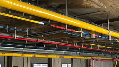
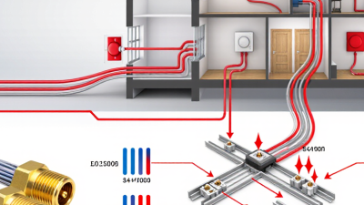
Choosing fire alarm cable in 2026 is not just a matter of picking a spool with the right label. The cable must suit the system design, installation environment, and project requirements. A crowded ceiling, a damp service room, and a long corridor can each raise different questions. Small details matter.
Fire protection engineer Wayne D. Moore is known for his work on fire alarm systems. A paraphrase, not a verbatim quotation, of a systems-based principle associated with his work is: “Choose cable as part of the complete fire alarm system, not as an isolated product.” That is a useful starting point. The right fire alarm cable depends on how the circuit is used, how it is installed, and what the system documentation specifies. Check conductor size, insulation, shielding, temperature rating, and fire-performance classification against the project requirements. Labels alone are not enough.
This guide explains the key selection factors, including cable types, ratings, installation conditions, and common purchasing mistakes. It also considers how requirements can differ by project and location, so confirm details with the design documents and qualified professionals. A mismatch may look harmless on a product sheet. It may not be harmless in the field. And product names can be confusing. Some advice may seem obvious, but it is worth checking twice before ordering.
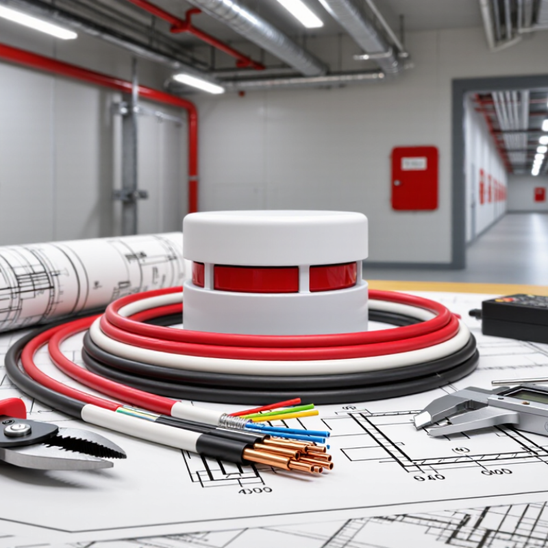
How to Choose Fire Alarm Cable in 2026
Fire alarm cable is a working part of a life-safety system, not just a connection between devices. It carries power and signals between control panels, detectors, sounders, and manual call points. During an emergency, those connections need to function as designed. Every detail matters. Cable type, insulation, and fire-resistance rating should match the system design and the conditions along the route. A ceiling void, a damp service area, and a crowded riser can present very different demands.
Tips: Check the project specifications and local requirements before selecting cable. Confirm conductor size, voltage rating, shielding needs, and compatibility with connected equipment. Inspect the route, too: sharp edges, tight bends, and nearby electrical circuits may affect installation. Keep cable identification clear at both ends. Small labels save time during testing.
A suitable cable alone cannot guarantee system performance. Correct supports, joints, terminations, and separation from other services matter just as much. Follow the equipment instructions and have qualified professionals verify the design and installation. Testing should confirm that circuits operate as intended, including any required fault monitoring. One detail is easy to miss: future maintenance access. A neatly installed cable hidden behind a finished ceiling may be difficult to inspect later. Planning for access is less exciting than choosing a rating, but it can make a real difference.
| Selection Factor | What to Check | Typical Options or Considerations | Why It Matters |
|---|---|---|---|
| Applicable codes and approvals | Confirm the adopted electrical and fire codes, local amendments, and authority having jurisdiction (AHJ) requirements. | In the United States, fire alarm cable requirements are commonly addressed under NFPA 70, Article 760. Requirements differ by location and project. | Code compliance depends on the installation and jurisdiction; a cable designation alone does not establish that an entire system is compliant. |
| Cable listing for installation space | Match the cable marking to the space and wiring method where it will be installed. | FPL is generally used for fire alarm circuits where permitted; FPLR is listed for riser applications; FPLP is listed for plenum applications. | Riser and plenum spaces have specific fire and smoke performance requirements. Confirm permitted substitutions and installation details in the applicable code. |
| Required circuit survivability | Determine whether a circuit must continue operating during a fire or other emergency condition. | Some systems or pathways may require a listed circuit-integrity cable, a protected pathway, or another approved survivability method. | Ordinary fire alarm cable is not automatically fire-resistive. Survivability requirements apply to the designed pathway or circuit as specified by code and the system design. |
| Conductor size and voltage drop | Check circuit length, conductor resistance, connected-device load, and the equipment manufacturer's voltage limits. | Common fire alarm cable conductor sizes include 18 AWG and 16 AWG; larger conductors may be needed for longer runs or higher loads. | Correct sizing helps ensure notification appliances and other powered devices receive adequate voltage under the calculated operating conditions. |
| Signal circuit type | Identify whether the cable serves a signaling line circuit, initiating device circuit, notification appliance circuit, or another function. | Conductor count, gauge, circuit class, topology, and permitted wiring method depend on the system design and equipment documentation. | Different circuits have different electrical and installation requirements. Use the system drawings and manufacturer instructions rather than selecting by appearance alone. |
| Shielding and interference | Check equipment documentation and assess nearby sources of electrical noise. | Use shielded cable only when required or permitted by the system design. Follow the specified grounding and shield-termination method. | Improper shielding or grounding can cause communication problems. Shielding does not replace correct separation, routing, or installation practices. |
| Environment and physical protection | Review temperature, moisture, sunlight, chemicals, abrasion, and exposure to physical damage along the route. | Select cable and raceway suitable for the actual environment; use listed outdoor or wet-location cable where required. | A cable suitable for an indoor space may not be suitable for outdoor, wet, corrosive, or mechanically exposed conditions. |
| Compatibility and documentation | Verify conductor requirements, terminal capacity, cable capacitance or resistance limits, and approved wiring methods. | Check the control equipment and device documentation, circuit schedules, and project specifications before ordering. | Compatibility supports reliable signaling and helps avoid installation changes, commissioning delays, or system faults. |
| Installation and identification | Plan routing, separation from other services, support, bend radius, splices, and circuit labeling. | Follow the applicable code, approved plans, and cable manufacturer's installation instructions. Identify conductors and circuits clearly. | Consistent installation and labeling make inspection, testing, troubleshooting, and future maintenance safer and more efficient. |
| Final verification | Have the selected cable and installation reviewed against the approved design and local requirements. | Confirm markings, listing, conductor specifications, pathway requirements, and inspection or acceptance-testing documentation. | For life-safety systems, confirm decisions with the qualified fire alarm designer or installer and the AHJ. Requirements may vary by project and jurisdiction. |